Inductive Conductivity (ISC) ■ Input Specification Compatible with
the Yokogawa inductive conductivity ISC40 series with integrated
temperature sensor: NTC30k or Pt1000. ■ Input Range Conductivity: 0
to 2000 mS/cm at 25 ºC reference temperature. Temperature: -20 to
140 ºC Cable length: max. 60 meters total length of fixed sensor
cable + WF10(J) extension cable. Influence of cable can be adjusted
by doing an AIR CAL with the cable connected to a dry cell. ■
Output Range Conductivity: min. span: 100 µS/cm max. span: 2000
mS/cm (max 90% zero suppression) Temperature: min. span 25 ºC max.
span 160 ºC ■ Performance (Accuracy) (The specifications are
expressed with simulated inputs.) (Output span is 0-100 µS/cm or
more) Conductivity: Linearity: ±(0.4 %F.S. + 0.3 µS/cm)
Repeatability: ±(0.4 %F.S. + 0.3 µS/cm) Temperature: ±0.3 ºC Step
response: 90 % (< 2 decades) in 8 seconds Note: "F.S." means
maximum setting value of analyzer output. 2-4. Dissolved Oxygen
(DO) ■ Input Specification The FLXA202 accepts output from membrane
covered Dissolved Oxygen sensors. These sensors can be Galvanic
type, where the sensor generates its own driving voltage or
Polarographic type, where the sensor uses external driving voltage
from the converter. The input range is 0 to 50 µA for Galvanic
sensors and 0 to 1 micro A for Polarographic sensors. For
temperature compensation, the FLXA202 accepts Pt1000 (DO30 sensor)
and NTC22k elements (OXYFERM and OXYGOLD sensors). ■ Input Range
DO30 sensor: Dissolved Oxygen: 0 to 50 mg/l (ppm) Temperature: -20
to 150 ºC Note: Process temperature for DO30 is 0 to 40 ºC Hamilton
sensors: Oxyferm: Measurement range: 10 ppb to 40 ppm Temperature
range: 0 to 130 ºC Oxygold G: Measurement range: 2 ppb to 40 ppm
Temperature range: 0 to 130 ºC Oxygold B: Measurement range: 8 ppb
to 40 ppm Temperature range: 0 to 100 ºC ■ Output Range DO
concentration: mg/l (ppm): min.: 1 mg/l (ppm) max.: 50 mg/l (ppm)
ppb: min.: 1 ppb max.: 9999 ppb % saturation: min.: 10 % max.: 600
% Temperature: min. span 25 ºC max. span 170 ºC ■ Performance
(Accuracy) (The specifications are expressed with simulated
inputs.) Performance in ppm mode: Linearity: ±0.05 ppm or ±0.8%
F.S., whichever is greater Repeatability: ±0.05 ppm or ±0.8% F.S.,
whichever is greater Accuracy: ±0.05 ppm or ±0.8% F.S., whichever
is greater Performance in ppb mode: Linearity: ±1 ppb or ±0.8%
F.S., whichever is greater Repeatability: ±1 ppb or ±0.8% F.S.,
whichever is greater Accuracy: ±1 ppb or ±0.8% F.S., whichever is
greater Temperature Linearity: ±0.3 ºC Repeatability: ±0.1 ºC
Accuracy: ±0.3 ºC Note: "F.S." means maximum setting value of
analyzer output. 2-5. pH/Oxidation-reduction Potential (pH/ORP)
with digital sensor, FU20F pH/ORP SENCOM Sensor ■ Input
Specification Bi-directional digital communication (RS-485) between
FU20F and FLXA202 ■ Input Range (depending on FU20F) pH: 0 to 14 pH
ORP: -1500 to 1500 mV rH: 0 to 100 rH Temperature: -10 to 105 ºC ■
Output Range pH: min. span 1 pH max. span 20 pH ORP: min. span 100
mV max. span 3000 mV rH: min. span 2 rH max. span 100 rH
Temperature: min. span 25 ºC max. span 170 ºC Feb. 02, 2016-00 4
All Rights Reserved. Copyright © 2015, Yokogawa Electric
Corporation GS 12A01A03-01EN 3. Electrical ■ Output Signal General:
One output of 4-20 mA DC Note: Tolerance: ±0.02 mA Bi-directional
HART digital communication, superimposed on mA (4-20mA) signal
Output function: Linear or Non-linear (21-step table) Burn out
function: (NAMUR 43 except ISC) Without HART/PH201G: Down: 3.6 mA
(signal: 3.8 to 20.5 mA for pH/ORP, SC and DO) (signal: 3.9 to 20.5
mA for ISC) Up: 22mA With HART/PH201G: Down: 3.6 mA for pH/ORP, SC
and DO Down: 3.9 mA for ISC (signal: 3.8 to 20.5 mA for pH/ORP, SC
and DO) (signal: 3.9 to 20.5 mA for ISC) Up: 22mA ■ Power Supply
Nominal 24 V DC loop powered system One (1) Sensor module (1
input): 16 to 40V DC (for pH/ORP (analog sensor), SC and DO) 17 to
40V DC (for ISC) 21 to 40V DC (for pH/ORP SENCOM sensor) Two (2)
Sensor modules (2 inputs): 22.8 to 40V DC (for pH/ORP (analog
sensor), SC and DO) Note: When the FLXA202 is used in the
multi-drop mode of HART communication, the output signal is changed
from 12.5 mA DC to 4 mA DC just after the power is turned on.
Enough power supply for the instruments is to be provided. Figure 1
Supply Voltage and Load Resistance for pH/ORP (analog sensor), SC
and DO Figure 2 Supply Voltage and Load Resistance for ISC and
pH/ORP SENCOM sensor Feb. 02, 2016-00 ● Maximum Load Resistance
pH/ORP (analog sensor), SC and DO: Refer to the Figure 1. ISC and
pH/ORP SENCOM sensor: Refer to the Figure 2. ■ Display LCD with a
touch screen: Black/White: 213 x 160 pixels Contrast adjustment
available on the touch screen Message language: 12 (English,
Chinese, Czech, French, German, Italian, Japanese, Korean, Polish,
Portuguese, Russian and Spanish) One analyzer has all 12 languages.
Note: Description for a selection of language and language names
are written in English. Note: Only English alphabet and numeric are
available for a tag number, an additional description for each
value on the display screen and passwords. Note: Only for message
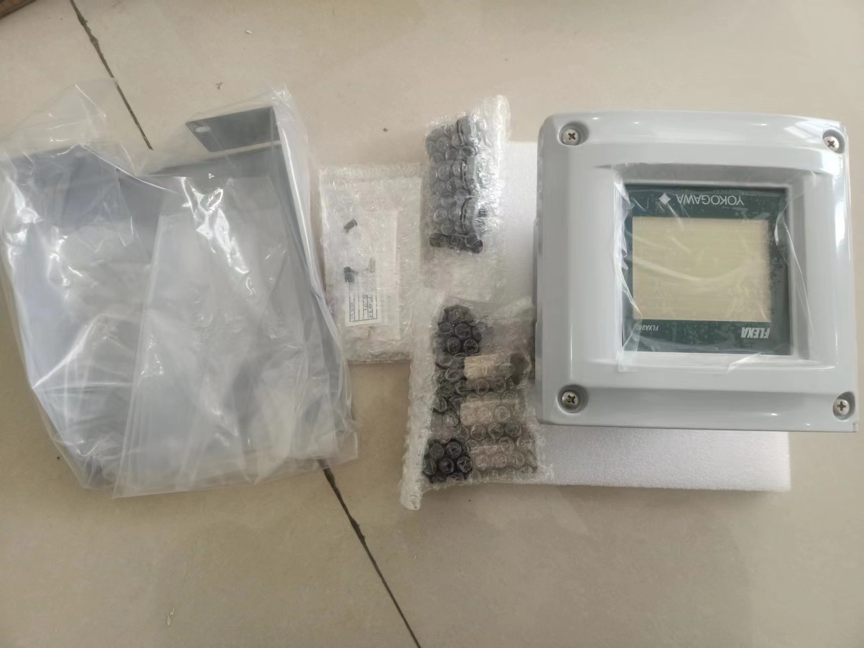
language on the screen, 12 languages are provided. 4. Mechanical
and others ■ Housing Case, Cover: • Aluminum alloy cast + epoxy
coating • Aluminum alloy cast + urethane coating • Aluminum alloy
cast + high anti-corrosion coating Color: Silver gray Protection:
IP66 (except Canada), Type 4X (except Canada), Type 3S/4X (Canada)
■ Cable and Terminal Cable size: Outer diameter: 6 to 12 mm
(suitable for M20 cable gland) Terminal screw size: M4 torque of
screw up: 1.2 N•m Wire terminal: Pin terminal, ring terminal and
spade terminal can be used for analyzer’s power supply terminals
and sensor terminals. Grounding terminal: Ring terminal should be
used. Pin terminal: pin diameter: max. 1.9 mm Ring and spade
terminal: width: max. 7.8 mm ■ Cable Entry 3 holes, M20 cable gland
x 3 pcs Close up plug x 1 pc Note: Cable gland and plug are
delivered with an analyzer, but not assembled into the analyzer. ■
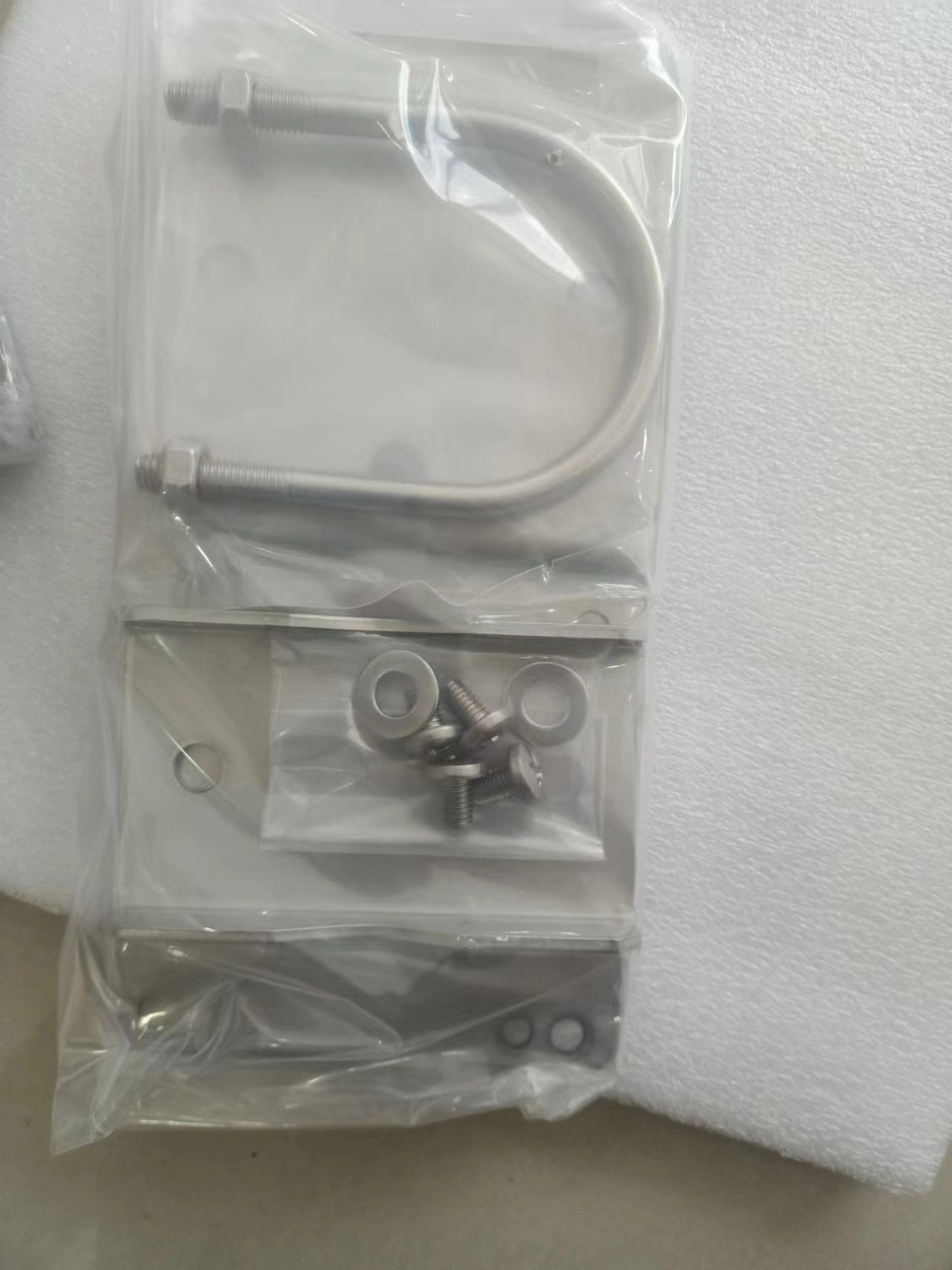
Mounting Mounting hardware (option): • Universal mounting kit
(Note) • Pipe and wall mounting hardware • Panel mounting hardware
Note: This kit contains the pipe and wall mounting hardware and the
panel mounting hardware. Hood (option): • Stainless steel •
Stainless steel with urethane coating • Stainless steel with epoxy
coating ■ Stainless Steel Tag Plate When the additional code “/SCT”
with a tag number is specified, the tag plate on which the tag
number is inscribed is delivered with the analyzer. Tag plate is
hanging type. 250 600 1000 0 18 24.7 V - 11.5 0.022 R = 1295 1617
22.8 40 Voltage (V) 2-sensor measurement Load resistance (Ω)
Digital Communication Range (HART) 250 304 600 516 1000 0 18 24.7 V
- 11.5 0.022 R = 1295 17 22.86 40 Except SENCOM Voltage (V) Load
resistance (Ω) Digital Communication Range (HART) 18.2 21 5 All
Rights Reserved. Copyright © 2015, Yokogawa Electric Corporation GS
12A01A03-01EN ■ Conduit Adapter Using optional adapter • G1/2
(quantity: 3) • 1/2NPT (quantity: 3) • M20 x 1.5 (quantity: 3)
These conduit adapters are delivered with an analyzer, but not
assembled into the analyzer. ■ Size of Housing Case 165 x 165 x 155
mm (W x H x D) (without cable gland) ■ Weight Approx. 2.5 kg ■
Ambient Operating Temperature -20 to +55 ºC ■ Storage Temperature
-30 to +70 ºC ■ Humidity 10 to 90% RH at 40ºC (Non-condensing) ■
Document Following documents are delivered with an analyzer; Paper
copy: Start-up Manual written in English Safety Precautions written
in English CD-ROM: Start-up Manual written in English User's Manual
written in English Safety Regulations Manual for European region
written in 25 languages General Specifications written in English
Technical Information for HART Communication written in English
User Setting Table of 5 kinds of measurement/sensor type written in
English ■ Regulatory Compliance Safety: UL 61010-1 UL 61010-2-030
CAN/CSA-C22.2 No.61010-1 CAN/CSA-C22.2 No.61010-2-030 EN 61010-1 EN
61010-2-030 EMC: EN 61326-1 Class A,Table 2 (For use in industrial
locations) EN 61326-2-3 AS/NZS CISPR11 RCM: EN 55011 Class A, Group
1 Korea Electromagnetic Conformity Standard Class A 한국 전자파적합성 기준
Installation altitude: 2000 m or less Category based on IEC 61010:
I (Note 1) Pollution degree based on IEC 61010: 2 (Note 2) Note 1:
Installation category, called over-voltage category, specifies
impulse withstand voltage. Equipment with “Category I” (ex. two
wire transmitter) is used for connection to circuits in which
measures are taken to limit transient overvoltages to an
appropriately low level. Note 2: Pollution degree indicates the
degree of existence of solid, liquid, gas or other inclusions which
may reduce dielectric strength. Degree 2 is the normal indoor
environment. Intrinsic safety and nonincendive (suffix code Type :
-CB, -CD, -DD): ATEX Intrinsic safety approval Applicable standard
Explosive Atmospheres EN 60079-0:2012/A11: 2013 Equipment - General
requirements EN 60079-11:2012 Equipment protection by Intrinsic
safety “i” EType of protection II 1 G Ex ia IIC T4 Ga Group: II
Category: 1G T4: for ambient temperature:–20 to 55ºC Atmosphere
pressure: 80kPa (0.8bar) to 110kPa (1.1bar) IECEx Intrinsic safety
approval Applicable standard IEC 60079-0: 2011 Part 0: Equipment -
General requirements IEC 60079-11: 2011 Part 11: Equipment
protection by Intrinsic safety “i” Type of protection Ex ia IIC T4
Ga T4: for ambient temperature:–20 to 55ºC Atmosphere pressure:
80kPa (0.8bar) to 110kPa (1.1bar) FM Intrinsic safety and
nonincendive approval Applicable standard Class-3600: 2011 Approval
Standard for Electric Equipment for use in Hazardous (Classified)
Locations General Requirement Class-3610: 2010 Approval Standard
for Intrinsically Safe Apparatus and Associated Apparatus for Use
in Class I, II, and III, Division 1, Hazardous (Classified)
Locations Class-3611: 2004 Nonincendive Electrical Equipment for
Use in Class I and II, Division 2 and Class III, Divisions 1 and 2,
Hazardous (Classified) Locations Class-3810: 2005 Electrical
Equipment for Measurement, Control and Laboratory Use ANSI/NEMA
250:2014 Enclosures for Electrical Equipment (1000 Volts Maximum)
ANSI/ISA 60079-0 2013 Part 0: General Requirements ANSI/ISA
60079-11 2014 Part 11: Equipment protection by intrinsic safety “i”
Type of protection Class I, Division 1, Groups A, B, C and D
(Intrinsically Safe) Class I, Division 2, Groups A, B, C and D
(Nonincendive) Class I, Zone 0, Groups IIC in Haza