Principle of the ultra-low frequency insulation voltage testThe ultra-low frequency insulation withstand voltage test is in
fact an alternative to the industrial frequency withstand voltage
test. As we know, in the test of large generators, cables and other
test products for industrial frequency withstand voltage test,
because their insulation layer presents a large electrical
capacity, so need a large capacity test transformer or resonant
transformer. Such some huge equipment, not only bulky, costly, and
very inconvenient to use. In order to solve this contradiction, the
power sector has adopted a reduced test frequency, thus reducing
the capacity of the test power supply. From the theoretical and
practical proof of many years at home and abroad, with 0.1Hz
ultra-low frequency withstand voltage test instead of frequency
withstand voltage test, not only can have the same equivalence, and
the volume of the equipment is greatly reduced, the weight is
greatly reduced, theoretically the capacity of about one fifth of
the frequency, and simple operation, compared with the frequency
test superiority more. This is the reason why this method is
commonly used in developed countries.
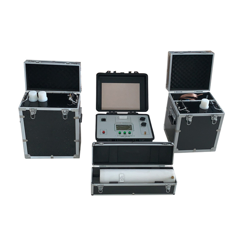
This product combines the advanced technology of modern digital
frequency conversion and adopts microcomputer control, which makes
boosting, bucking, measuring and protection completely automatic.
Because it is fully electronic, it is small in size and light in
weight. The large LCD display is clear and intuitive, and it can
display the output waveform and print test reports.
This product has the following characteristics1, rated voltage less than or equal to 50kV ultra-low frequency
using a single structure (a booster); more than 50kV ultra-low
frequency using a series structure (two boosters in series), so
that the overall weight is greatly reduced, the carrying capacity
is enhanced, and the two boosters can be used separately for low
voltage level ultra-low frequency.
2,Current, voltage and waveform data are obtained directly from the
high-voltage side sampling, so the data is accurate.
3,With over-voltage protection function, when the output exceeds
the set voltage limit value, the instrument will stop and protect,
the action time is less than 20ms.
4,With over-current protection function: designed for double
protection of high and low voltage, the high voltage side can be
stopped precisely according to the set value; the low voltage side
will be stopped when the current exceeds the rated current, the
action time is less than 20ms.
5,The high voltage output protection resistor is designed in the
booster body, so there is no need to connect another protection
resistor outside.
6,Because of the use of high and low voltage closed loop negative
feedback control circuit, the output has no capacitive rise effect.
| Model no | Rated Voltage | Load Carrying
Capacity | Power
FuseTube | Product Structure |
| XHDP-30 | 30kV
(Peak) | 0.1Hz,≤1.1µF | 8A | Controller
Booster |
| 0.05Hz,≤2.2µF |
| 0.02Hz,≤5.5µF |
| XHDP-50 | 50kV
(Peak) | 0.1Hz,≤1.1µF | 20A | Controller
Booster |
| 0.05Hz,≤2.2µF |
| 0.02Hz,≤5.5µF |
XHDP-60
| 60kV
(Peak) | 0.1Hz,≤1.1µF | 20A | Controller
Booster |
| 0.05Hz,≤2.2µF |
| 0.02Hz,≤5.5µF |
XHDP-80
| 80kV
(Peak) | 0.1Hz,≤1.1µF | 20A | Controller
Booster |
| 0.05Hz,≤2.2µF |
0.02Hz,≤5.5µF
|