The Inductive Loop Sensor redefines reliability in vehicle detection with its unparalleled
precision and self-monitoring capabilities, engineered for
demanding environments like toll lanes, industrial gates, and urban
intersections. Featuring 16-level sensitivity calibration (0-F), it achieves micron-level accuracy across a broad 15-2000μH inductance range, detecting vehicles from bicycles to heavy-duty trucks while
ignoring non-metallic objects like plastic barriers or debris. Its adaptive noise suppression dynamically filters interference from nearby motors, radio towers,
and EV chargers, ensuring 99.95% detection accuracy even in high-EMI zones. The sensor’s built-in diagnostics shine with real-time LED indicators for coil health (green =
normal, red = short, yellow = open) and a self-test mode that
generates automated reports via Bluetooth for proactive
maintenance. Encased in a UV-resistant ABS housing (IP65-rated), it withstands extreme temperatures (-30°C to +80°C), corrosive
road salts, and prolonged UV exposure, making it ideal for both
indoor and sheltered outdoor installations.
Beyond its rugged design, the sensor simplifies integration into
modern systems. The universal 12-24V DC/100-240V AC input supports solar-powered and grid-connected setups, while the configurable relay output (NO/NC, 0.5A @ 120VAC) interfaces seamlessly with barriers, traffic lights, and IoT
platforms. For smart cities, its Modbus RTU compatibility enables real-time data streaming to traffic management systems
(TMS), empowering adaptive signal control and congestion analytics.
In a recent pilot at a German logistics hub, the sensor reduced
false triggers by 90% and maintenance costs by 40% through
predictive diagnostics. Certified for CE, FCC, and RoHS, it also features auto-reset functionality to recover from power surges or transient faults without manual
intervention.
From airport tarmacs monitoring ground service vehicles to retail drive-thrus optimizing queue times, this sensor delivers unmatched
versatility. For industrial complexes, its precision ensures AGVs
navigate safely without misreads, while toll operators leverage its
EMI immunity to prevent revenue loss from missed detections. Backed
by a 7-year warranty and 24/7 technical support, the Inductive Loop Sensor is the
ultimate blend of precision, durability, and intelligence—proving
that single-channel solutions can outperform bulkier, costlier
alternatives.
Features
- 1. 15-2000 μh detection Range
- The loop detector supports a wide detection range from 15 µH to
2000 µH, accommodating various loop sizes and configurations for
versatile application in different traffic detection scenarios. The wide detection range enables our loop detector to detect all
kinds of vehicles, motorcycles, cars, Ultra long truck, buses and
so on.
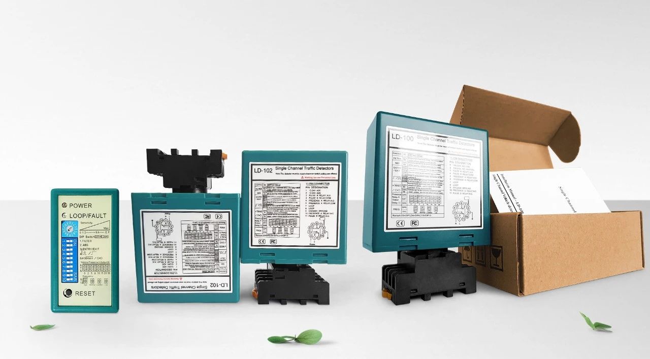
- 2. Compact Side
- The compact and well-engineered housing combines all industry
requirements for features and functionality, allowing this detector
to be incorporated into any existing traffic detection system.
- 3. LED Diagnostic Capabilities
- Comprehensive diagnostics capabilities enable accurate diagnosis of
loop and installation problems and shows through LED, ensuring
optimal performance and reducing downtime.
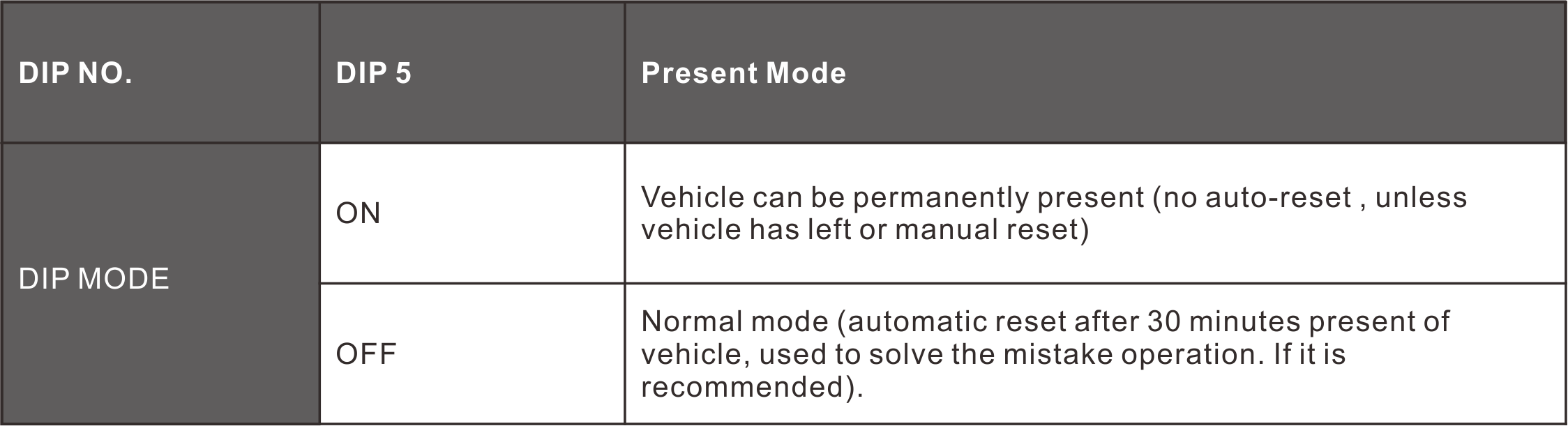
- 4. Selectable Presence Time
- The output of the presence relay can be selected to limit a detect
output to a fixed time (greater than 30 minutes) while a vehicle
remains on the loop, providing flexibility in traffic management.
- 5. Loop Presence Time
- Interference between adjacent loop detectors can be identified
through integral indication and eliminated by adjusting the
frequency setting, ensuring reliable operation.
- 6. Two Separate Output Relays
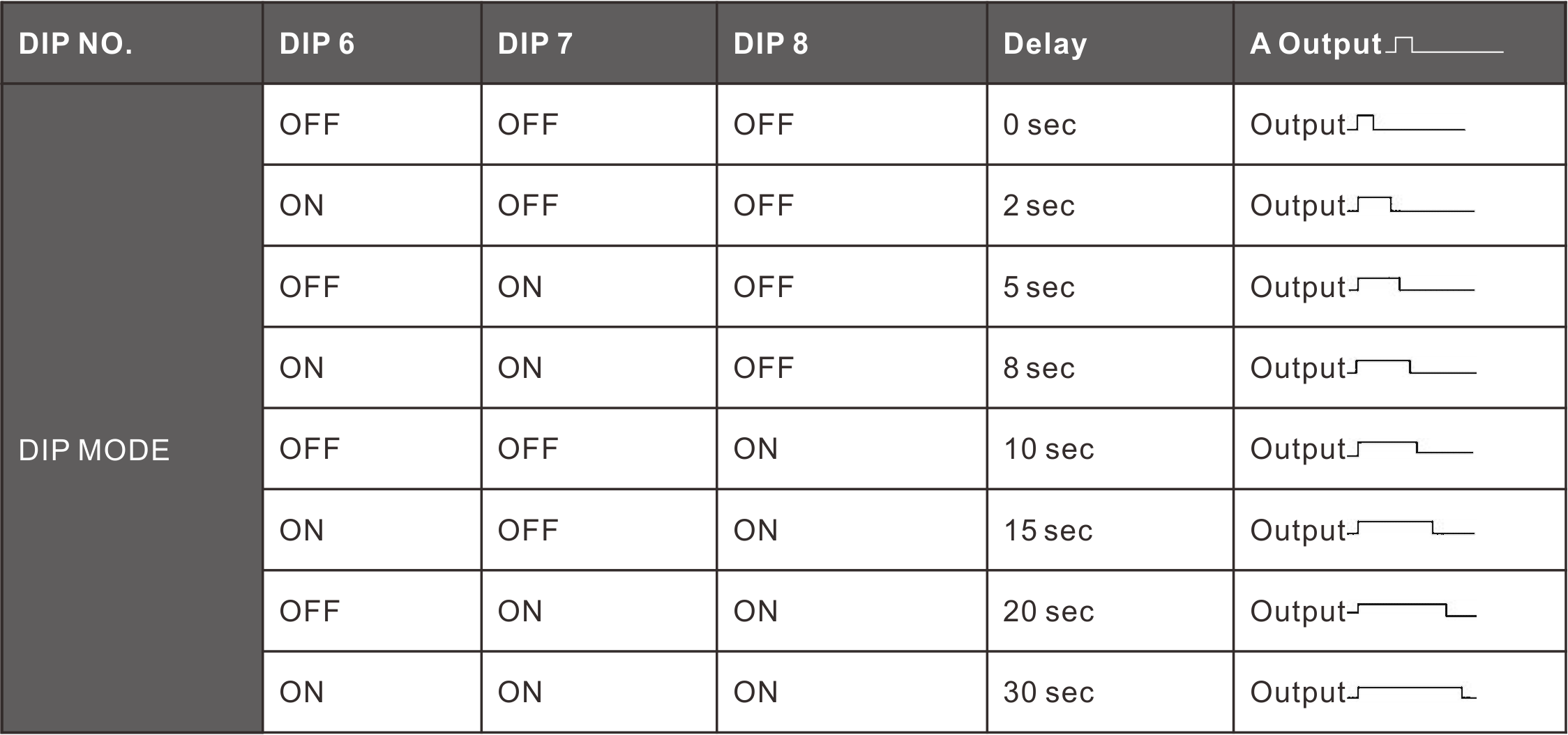
- Presence Relay A: Provides presence output and can be extended for
0, 2, 5, 8, 10, 15, 20, or 30 seconds, programmable with external
10-way DIP switches.
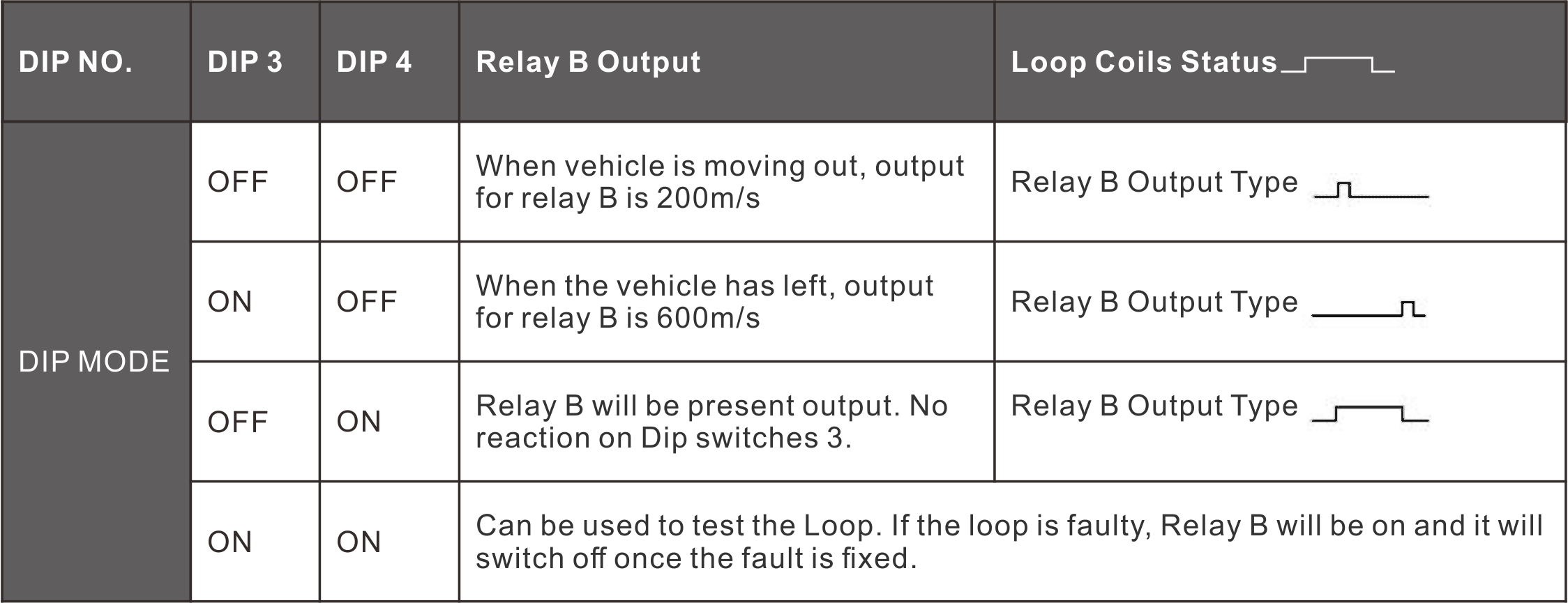
- Pulse Relay B: Programmable with external 10-way DIP switches, it
offers presence, pulse on entry, pulse on exit, or failed output,
enhancing detection flexibility.
- 7. Automatic Sensitivity Boost (ASB)
- This feature reliably detects large truck-trailer combinations and
high-bed vehicles by automatically boosting the sensitivity to
maximum upon vehicle detection, ensuring accurate identification.
- 8. Automatic Environment Drifting Compensation
- Loop detectors (or other sensors) automatically adjust and
calibrate themselves to changes in environmental conditions,
maintaining detection accuracy and stability despite varying
weather and environmental factors.
- 9. 10 Dip Switch
- The dip swich design on the shell makes the setting of loop
detector easier and clearer, which is very user-friendly for users.
Users can set all the functions first and then install the loop
detector.
- 10. Anti-crosstalk interference.
- Through the dip Switch, the frequency of the loop detector can be
adjusted to prevent crosstalk interference caused by the
installation of two loop coils too close.
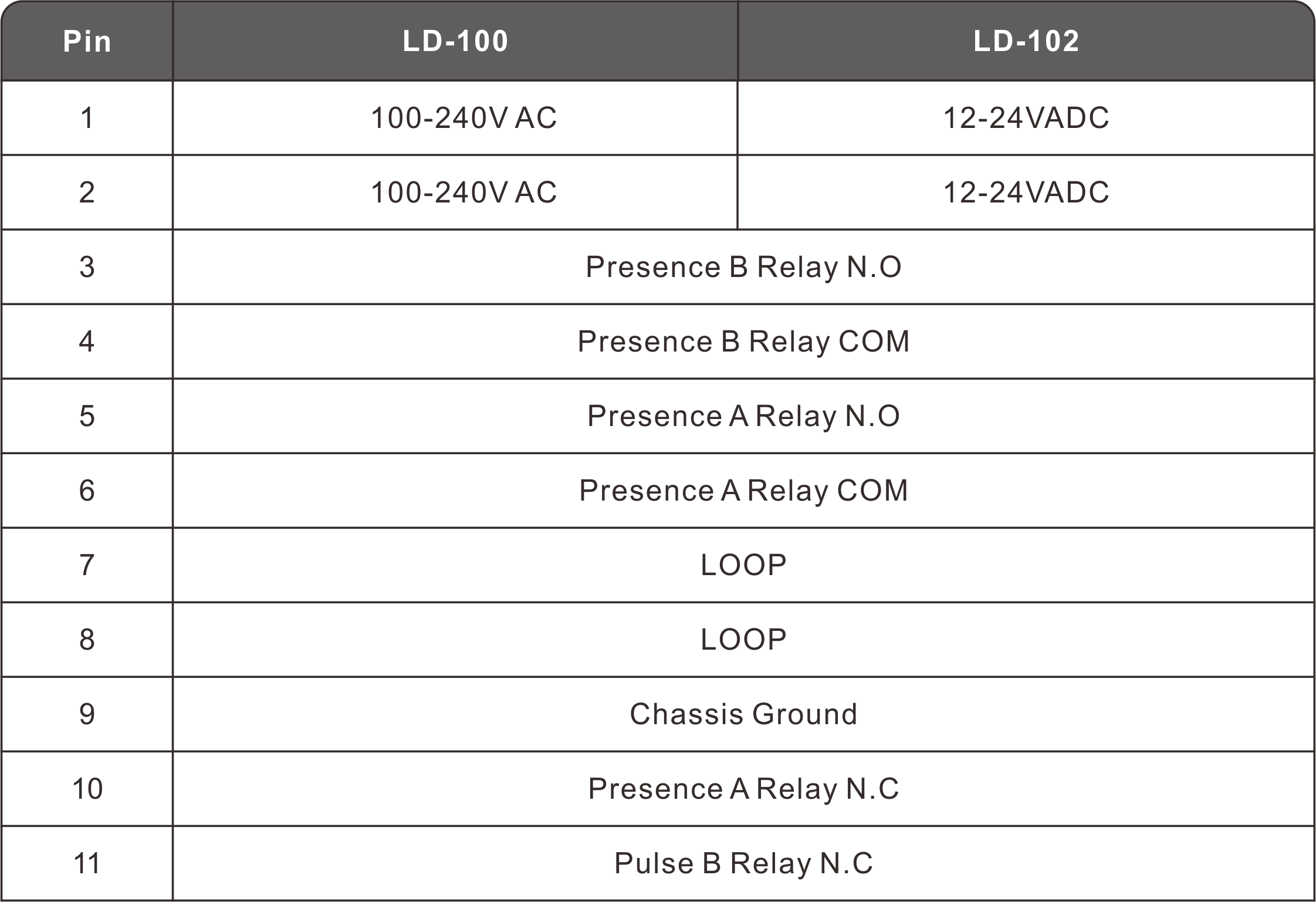
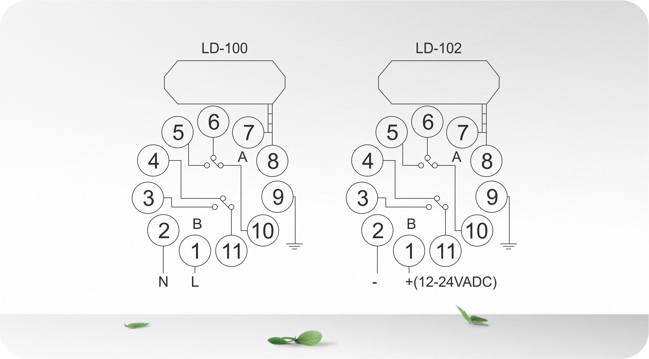
Connection
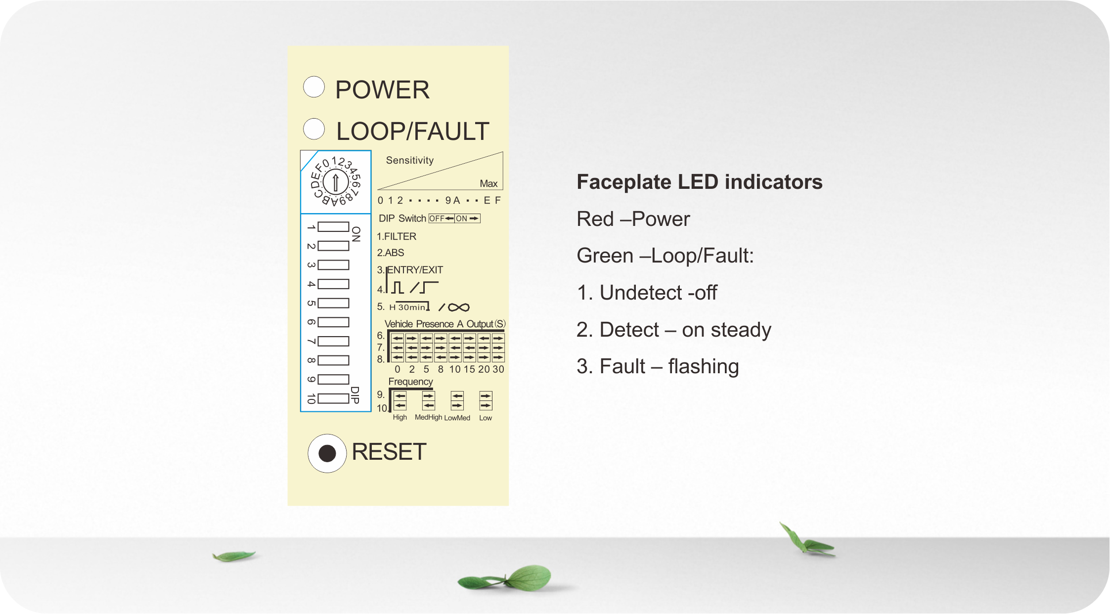
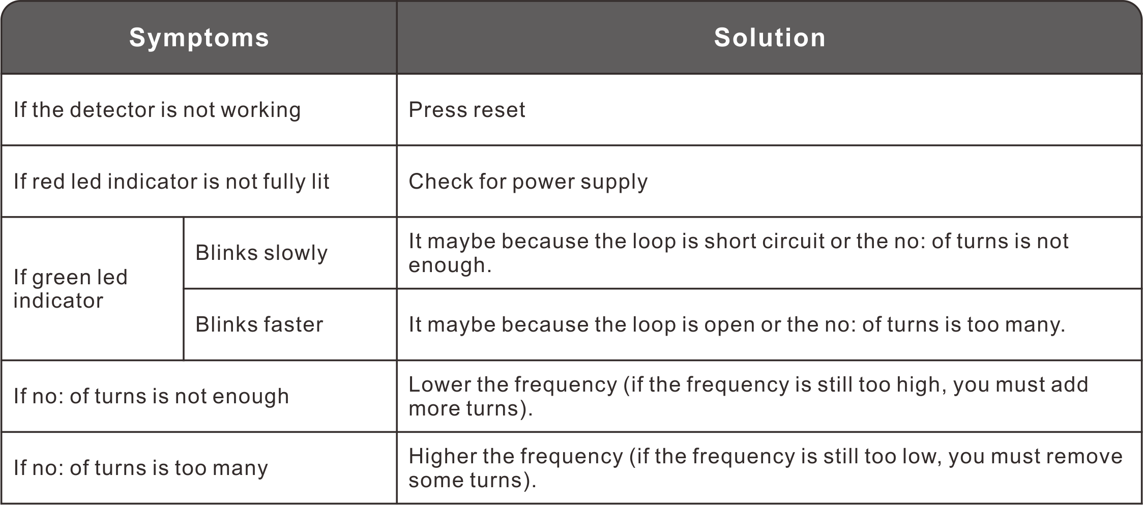
- Detecting Led: Continuously On: Indicates vehicle detection.
- Blinking slowly: Indicates loop is short circuit or the number of
twists after the loop is not enough.
- Blinking fast: Indicates loop is open circuit or too many twists
after the loop.
(2)Switch 1 (Trimpot), Sensitivity SelectionSensitivity of the loop can be adjusted by the trimpot labeled
“Sensitivity”. User can select 16 different setting by turning the trimpot with 0 being the least sensitive and “F”
being the most sensitive.

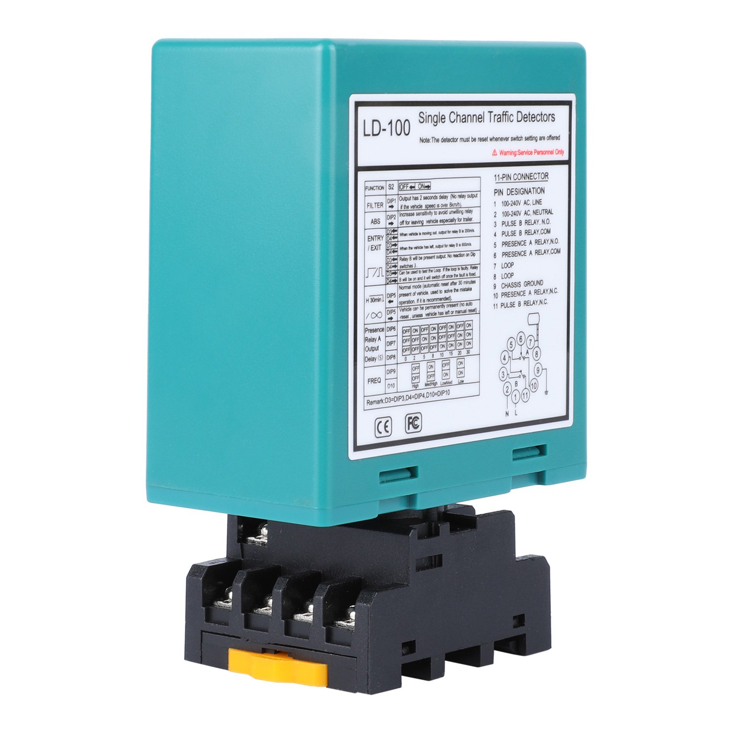
(3)Switch 2 (Dipswitch Settings)
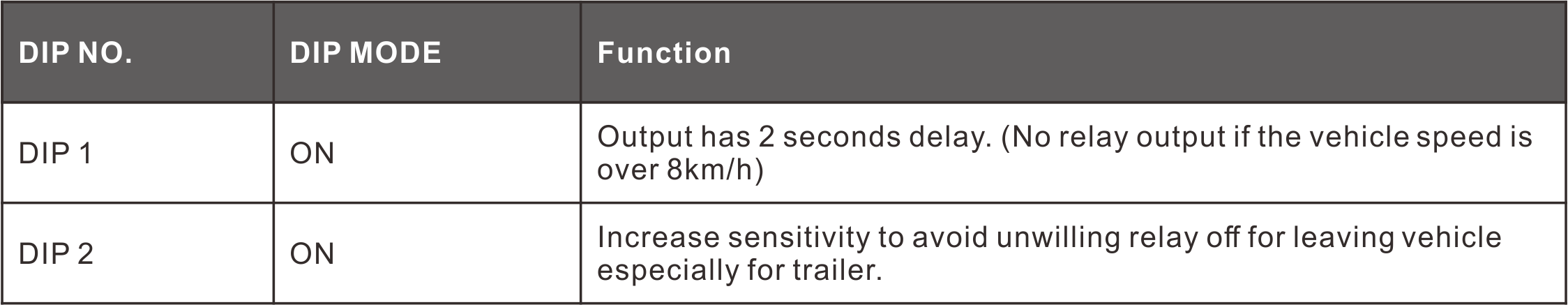
1.DIP 1 & DIP 2 Setting Special Functions
2. DIP 3 & DIP 4 Setting Relay B Output
3. DIP 5 Setting Automatic Reset
4. DIP 6 & DIP 7 & DIP 8 Setting Relay A Delay
5. DIP 9 & DIP 10 Setting Frequency (40 K to 100 KHz). Used to
avoid the interference
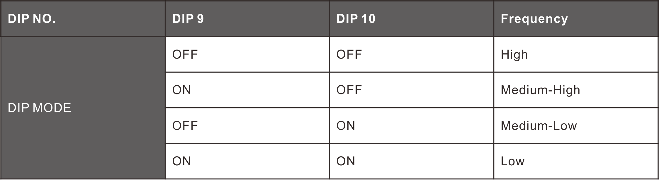
- In the application, where two or more loop detectors and sensing
loops have been installed, set one detector to high frequency and the other set to low frequency to
minimize the effects of cross-talk between the two systems(The
sensing loops and detectors should be positioned at least 2m
apart).
- Reset Button:Please note: The LD-100 must be reset every time a
setting change is made to the Dip switches.
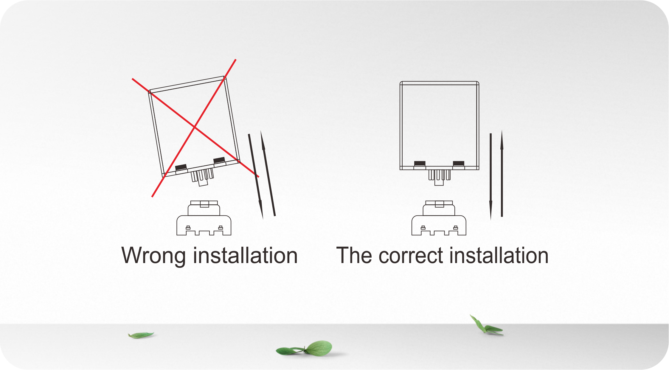
Detector Position And Installation:- Install the detector in a weatherproof housing.
- The detector should be as close to the sensing loop as possible.
- The detector should always be installed away from strong magnetic
fields.
- Avoid running high voltage wires near the loop detectors.
- Do not install the detector on vibrating objects.
When the control box is installed within 10 metres of the loop,
normal wires can be used to connect the control box to the loop.
More than 10 metres requires the use of a 2 core shielded cable. Do
not exceed 30 metres distance between control box and loop.
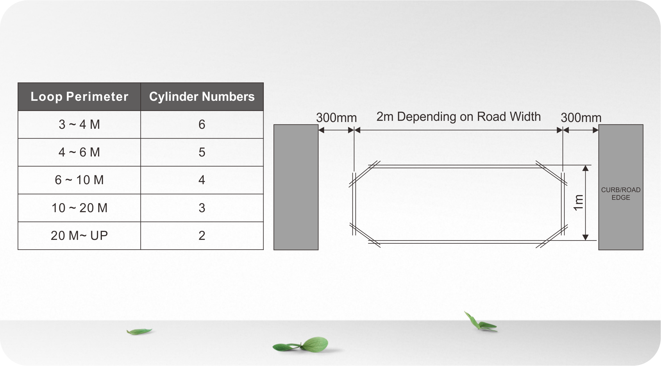
Loop Installation:
The loops are sealed using a “quick-set” black epoxy compound or
hot bitumen mastic to blend with the roadway surface.
Trouble Shooting:
Certification

Product Series
| LD-100 | LD-102 | LD-200 | LD-202 | JTHT-11 |
Single Channel 100-240 V AC | 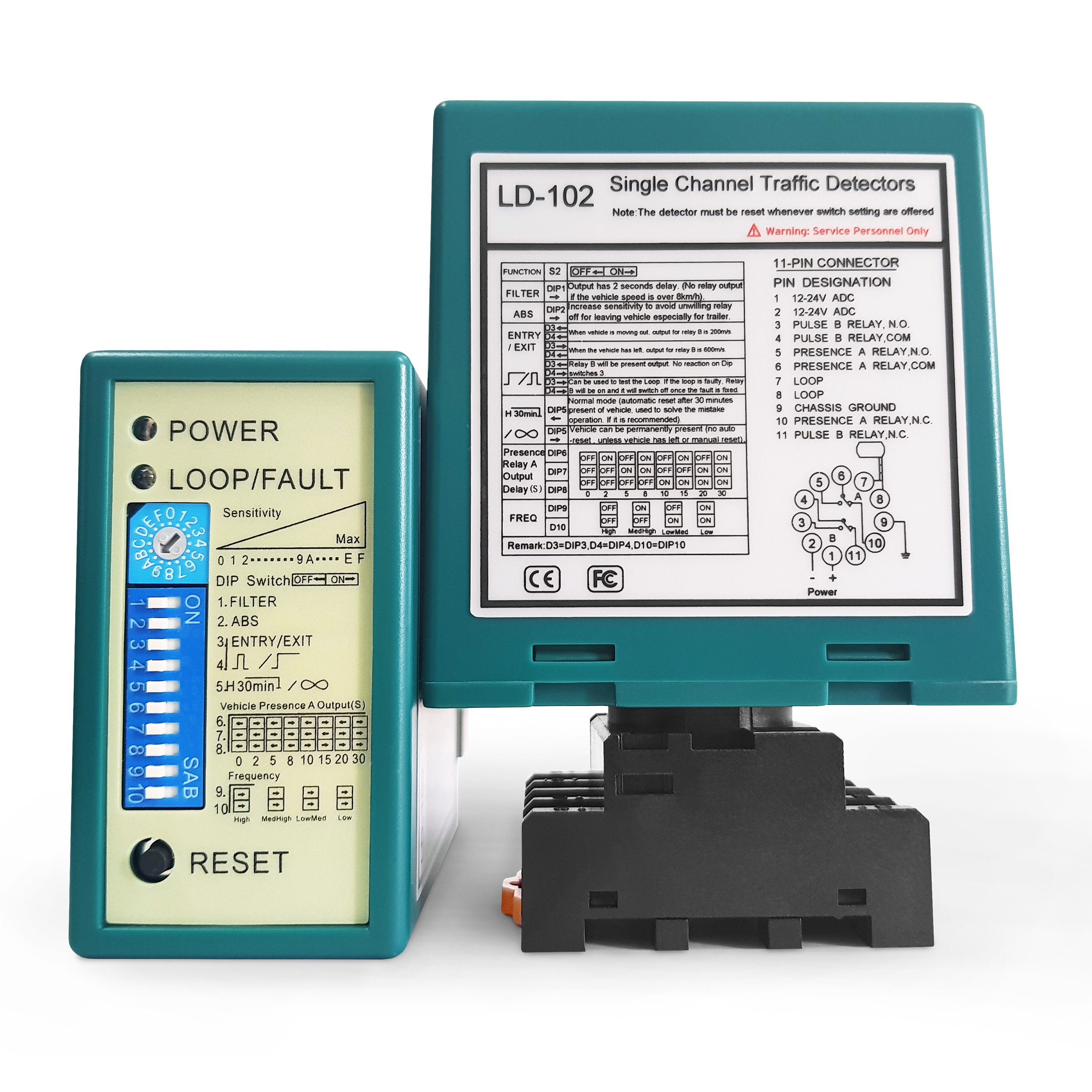
Single Channel 12-24 V AC/DC | 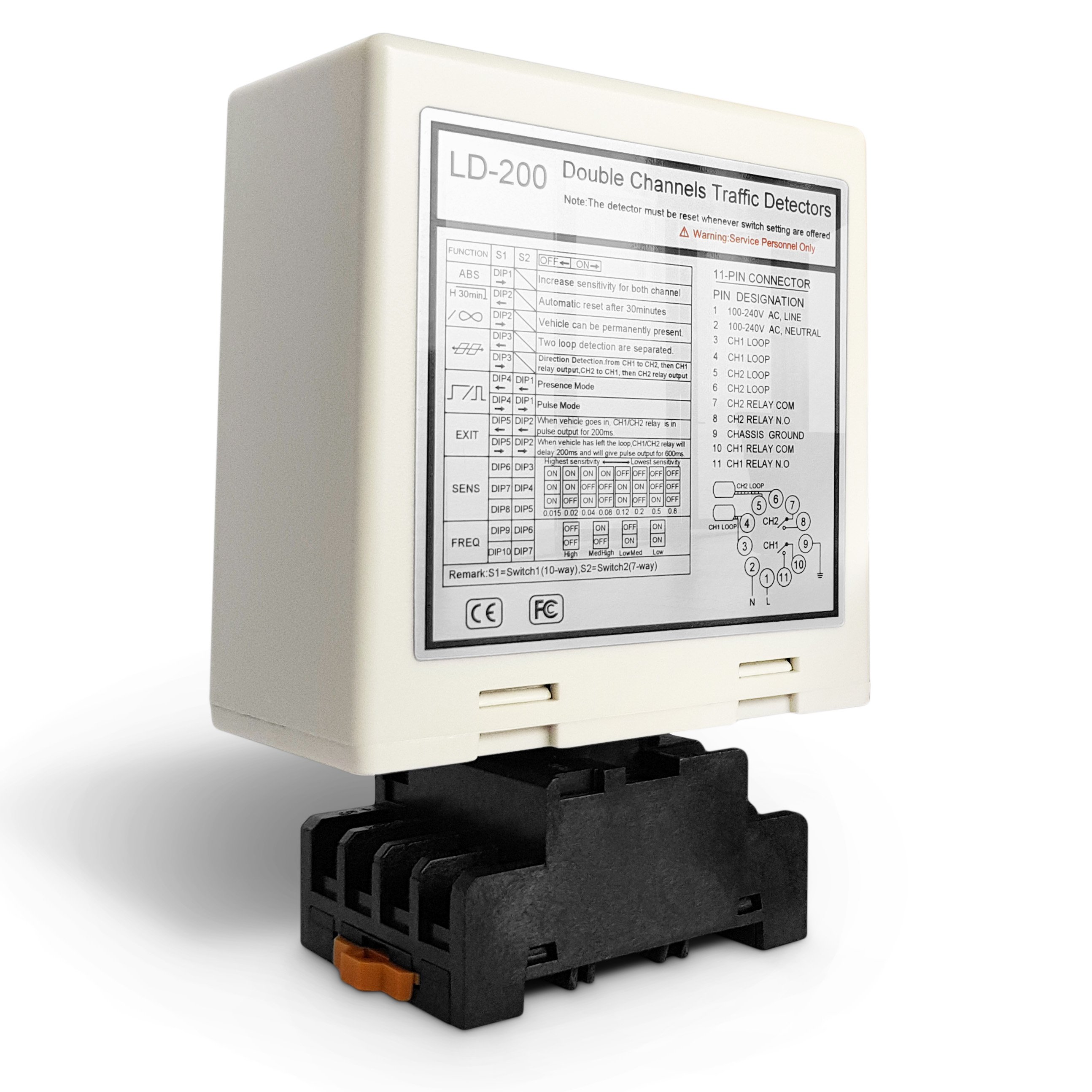
Dual Channel 100-240 V AC | 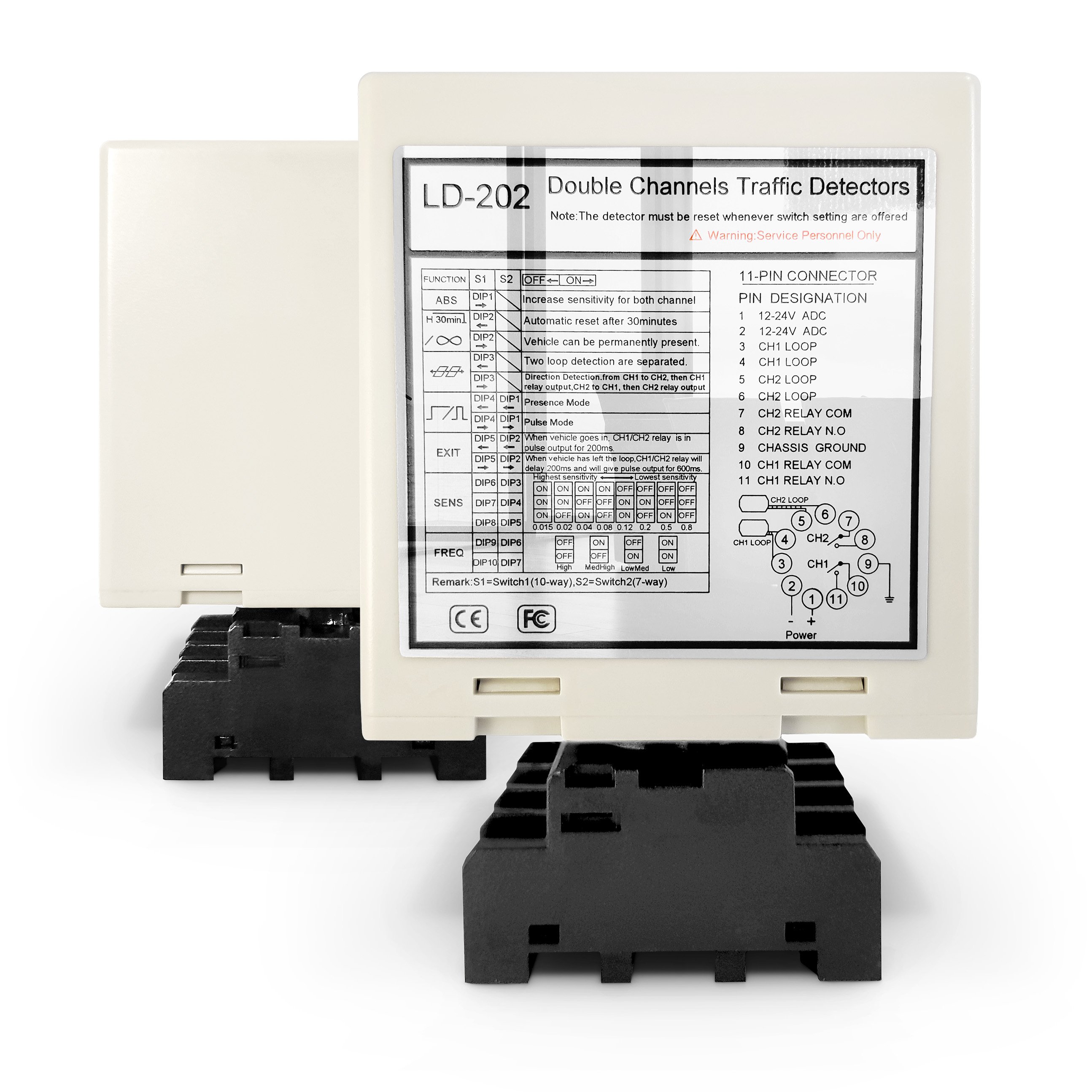
Dual Channel 12-24 V AV/DC | 
Loop cable 305 m Teflon coil |
| LCR-MT | | | | |
Multimeter | | | | |

