| Sign In | Join Free | My ecer.jp |
|
| Sign In | Join Free | My ecer.jp |
|
| Categories | Y Type Control Valve |
|---|---|
| Brand Name: | POWERFLOW |
| Model Number: | 2710+1600 |
| Certification: | ISO9001. CE. |
| Place of Origin: | CHINA |
| MOQ: | 1 Nos |
| Price: | Quotation Offered by Email. |
| Payment Terms: | T/T |
| Supply Ability: | 50Nos/Week for every single Customer. |
| Delivery Time: | 10-15 Days |
| Actuator Material: | Plastic/Stainless steel 304(CF8)/ 316(CF8M) |
| Seal Material: | PTFE/PPL |
| Working Pressure: | 16Bar |
| Working Temperature: | -20-220℃ |
| Available Connection: | Thread, Clamp, Flanged, Welding |
| Standard: | DIN, SMS, ISO, IDF,RJT, 3A, etc |
| Company Info. |
| POWERFLOW CONTROL CO,. LTD. |
| View Contact Details |
| Product List |
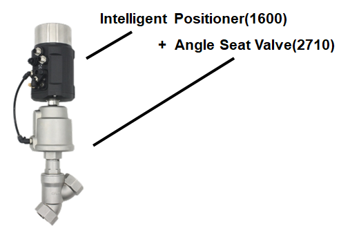
1. Product description
The angle seat control valve is combined with the smart positioner (1600) and the angle seat valve(2710).
1600 Series positioner can be operated via the keypad easily. It detects the signal of internal displacement sensor and the external setting signal, and adjusts valve stroke fast and precisely via PWM control technology and automatic control algorithm.
Compared to 2700 series angle seat valve, 2710 is with adjusting cones, so its flow characteristic is more suitable for the flow adjustment.
2. 2710 Angle Seat Valve Technical Datas
| Valve Body Material | Stainless steel 304(CF8)/ 316(CF8M) |
| Actuator Material | Plastic/ Stainless steel 304(CF8)/ 316(CF8M) |
| Seal Material | PTFE/ PPL |
| Working Pressure | 16Bar |
| Available Size | DN15 - DN100 |
| Working Temperature | -20 - 220℃ |
| Available Connection | Thread, Clamp, Flanged, Welding |
| Air Supply | 2.5 - 8Bar |
| Standard | DIN, SMS, ISO, IDF, RJT, 3A, etc |
| Certificate | CE |
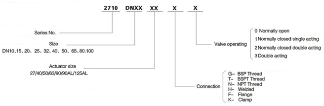
3. 2710 Type Selection
4. Dimension
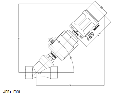
| Type | Actuator | D | R | G1 | H/LA | ||
|---|---|---|---|---|---|---|---|
| Screw thread | Welding ISO1127/4200 | Welding DIN11850 | |||||
| DN10 | 40 | 50.5 | 27 | G1/8 | 259 | 260 | 260 |
| 50 | 62 | 34 | G1/8 | 271 | 272 | 272 | |
| DN15 | 40 | 50.5 | 27 | G1/8 | 259 | 259 | 259 |
| 50 | 62 | 34 | G1/8 | 271 | 271 | 271 | |
| DN20 | 50 | 62 | 34 | G1/8 | 275 | 275 | 275 |
| DN25 | 50 | 62 | 34 | G1/8 | 281 | 281 | 281 |
| 63 | 77 | 41.5 | G1/8 | 303 | 303 | 303 | |
| DN32 | 63 | 77 | 41.5 | G1/8 | 311 | 311 | 311 |
| 80 | 98 | 52 | G1/4 | 328 | 328 | 328 | |
| DN40 | 63 | 77 | 41.5 | G1/8 | 319 | 319 | 319 |
| 80 | 98 | 52 | G1/4 | 335 | 335 | 335 | |
| 100 | 121 | 63 | G1/4 | 353 | 353 | 353 | |
| DN50 | 63 | 77 | 41.5 | G1/8 | 330 | 330 | 330 |
| 80 | 98 | 52 | G1/4 | 345 | 345 | 345 | |
| 100 | 121 | 63 | G1/4 | 363 | 363 | 363 | |
| DN65 | 80 | 98 | 52 | G1/4 | 370 | 370 | 370 |
| 100 | 121 | 63 | G1/4 | 387 | 387 | 387 | |
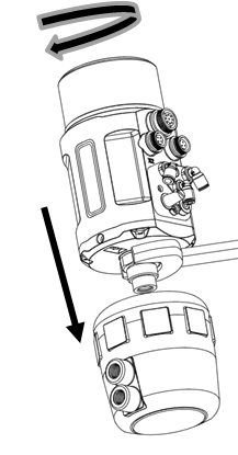
5. Assembling
The positioner and Valve is connected by thread. You can easily assemble them with a #32 wrench.
After assembling, the Positioner can still have 360°Rotation to fix to your favourite position
6. Schematic diagram


|
