| Sign In | Join Free | My ecer.jp |
|
| Sign In | Join Free | My ecer.jp |
|
| Categories | Plug Socket Tester |
|---|---|
| Brand Name: | SHC |
| Model Number: | SC-BS-F17a |
| Certification: | CNAS、TUV、ITS、CSA、BV、SGS (cost additional) |
| Place of Origin: | China |
| MOQ: | 1 piece |
| Price: | USD 50-2000 piece |
| Payment Terms: | T/T, Western Union, MoneyGram, L/C |
| Supply Ability: | 999 pieces per month |
| Delivery Time: | in 15 work days |
| Packaging Details: | Wooden Carton |
| Standards: | BS1363 Figure 17a |
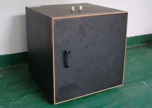
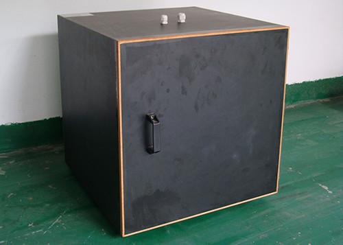
| Name: | Test Apparatus For Temperature Rise Test |
| Function: | For Temperature Rise Test |
| Test cabinet material: | 10mm nominal plywood |
| Test cabinet Finish: | Internal. Two coats of matt paint. BS4800 colour no.08 C35. |
| Test cabinet Dimensions: | Internal.500mmX500mmX500mm with a tolerance of +-10mm for each dimension. |
| Location: | inimum clearance from adjacent surfaces, measured horizontally 150mm on all sides, measured vertially 300mm above, 500mm below. |
| Wooden mounting block: | 1 |
BS1363 Figure17a Test Apparatus For Temperature Rise Test
Parameters:
| Standards | BS1363 Figure 17a |
| Function | For temperature rise test |
| Test cabinet Meterial | 10mm nominal plywood |
| Test cabinet Finish | Two coats of matt paint. BS4800 colour no.08 C35. |
| Dimensions | Internal.500mmX500mmX500mm with a tolerance of +-10mm for each dimension. |
Test cabinet Meterial: 10mm nominal plywood.
Test cabinet Finish: Internal. Two coats of matt paint. BS4800
colour no.08 C35.
Dimensions: Internal.500mmX500mmX500mm with a tolerance of +-10mm
for each dimension.
One will to be removable to provide access.
Location: Minimum clearance from adjacent surfaces, measured
horizontally 150mm on all sides, measured vertially 300mm above,
500mm below.
BS1363 List of references
Figure17a)-Test apparatus for temperature-rise- test
Figure 17b)-dummy front plate for temperature-rise test
Figure 18-apparatus for flexing test
Figure 19-solid link for test on fuse clips
Figure 20--tumbling barrel
Figure 21-pendulum impact test
Figure 23-apparatus for pressure test
Figure 24-apparatus for ball pressure test
Figure 28-calibrated link
Figure 29-calibration jig for calibrated link
Figure 30-test plug for temperature rise
Figure 32-apparatus for tests on adaptor pins
Figure 33-apparatus for torsion test on pins
Figure 34-test plug
Figure 35-simulated plug and cord devices
Figure 36-apparatus for calibration of turning moment of
simulated plug
Figure 37-turning moment apparatus
Figure 38-solid links for test on fuse clips
Figure1 test pin
Figure 2a)-apparatus for mechanical strength test on resilient
covers
Figure 2b)-hardwood block for Figure 2a)
Figure 3-disposition of socket contacts
Figure 4-dimensions and disposition of pins
Figure 5-gauge for adaptor pins
Figure 6-apparatus for testing plug cover fixing screws
Figure 7-mounting plate
Figure 8-plug pin deflection test apparatus for resilient adaptors
Figure 9-apparatus for abrasion test on insulating sleeves of plug
pins
Figure 10-apparatus for pressure test at high temperatures
Figure 11-GO gauge for socket-outlet
Figure 12-contact test gauge
Figure 13-test apparatus and circuit for use with contact and
non-contact test gauges
Figure 14-non-contact test gauge
Figure 16-withdrawal pull gauges for effectiveness of contact
|